
Preventing Sludge Container Overflow With an Ultrasonic Sensor
Sludge disposal containers at a water treatment facility can fill unevenly and faster than expected. Without reliable monitoring, sludge may reach the top of the container before operators can stop the loading process or arrange a replacement container.
An ultrasonic sensor mounted above the container can provide non-contact sensing of the sludge pile. By continuously measuring the distance between the sensor and the rising material, the facility’s control system can generate warnings, stop equipment, or notify personnel before an overflow occurs.
Quick Answer: Can an Ultrasonic Sensor Monitor a Sludge Container?
| Question | Answer |
| What problem does this solve? | Detects rising sludge before it reaches the top of a roll-off container, helping prevent spills, cleanup, equipment contamination, and process interruptions. |
| Best fit for ultrasonic sensing? | Applications where the sensor can be mounted above the container with an unobstructed path to a representative area of the sludge pile. |
| Typical measurement needed | Continuous distance measurement over approximately 4 to 144 inches. |
| Output type | 0–10 V analog voltage output to a PLC, controller, meter, or monitoring system. |
| Suggested Migatron sensor | RPS-409A-40 ultrasonic sensor. |
| When to contact engineering | When the sludge surface is highly irregular, the loading stream crosses the beam, the sensor may be exposed to heavy buildup, or multiple sensors will operate near each other. |
Application Overview
In many municipal and industrial wastewater operations, sludge is discharged from a conveyor, screw press, centrifuge, belt press, or similar processing system into a roll-off container.
The sludge does not always form a level surface. It may create a cone shaped pile directly below the discharge point, collect more heavily at one end, or collapse and shift as additional material is added. Operators therefore need to monitor a location that represents the container’s practical fill condition rather than assuming the material is evenly distributed.
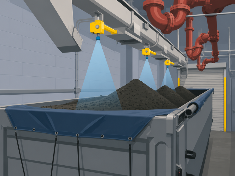
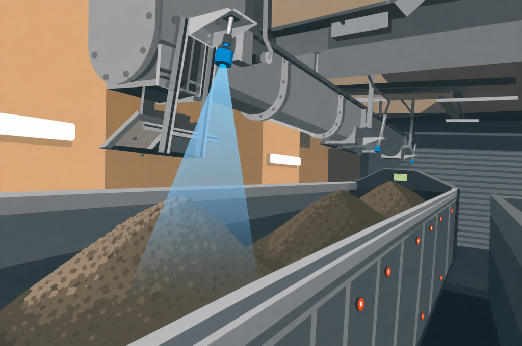
A non-contact ultrasonic sensor can be mounted above the container and aimed downward at the sludge pile. Because the sensor does not touch the material, there are no floats, probes, or mechanical switches extending into the sludge.
This approach can help a water treatment facility:
- Warn operators when the container is approaching capacity.
- Stop or redirect the sludge-loading process at a defined level.
- Provide fill-status information to a PLC or SCADA system.
For a municipal planner evaluating facility upgrades, the same basic installation can also be incorporated into a scalable sensor network. Individual container stations can report analog measurements to a central control system, allowing operators to monitor multiple disposal points from one location.
How Ultrasonic Sensors Work in This Application
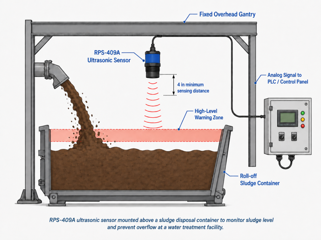
An ultrasonic sensor emits a high-frequency sound pulse toward the sludge surface. The sound reflects from the material and returns to the sensor.
The sensor measures the time required for the pulse to travel to the sludge and back. This time-of-flight measurement is converted into the distance between the sensor face and the top of the pile.
As the sludge level rises, the measured distance decreases. The sensor’s analog voltage output changes with that distance and can be read by a PLC or other analog input device.
The control system can then convert the voltage into a usable value such as:
- Distance from the sensor.
- Approximate sludge height.
- Percentage of available container capacity.
For this application, the control logic should generally use a short averaging period or time delay. This can prevent a single piece of falling sludge or a temporary surface movement from triggering an unnecessary alarm.
Will Ultrasonic Sensing Work Here?
Ultrasonic sensing is usually a good fit when:
- A clear beam path is available between the sensor and the target.
- The sensor is aimed at a representative section of the pile.
- The sludge surface provides a consistent reflected echo.
Ultrasonic sensing may need review when:
- The sludge pile forms outside the selected measurement area.
- The container position changes significantly after each replacement.
- The required measurement distance exceeds the selected sensor range.
An application test is recommended when the sludge composition, surface shape, or mounting arrangement is uncertain.
Key Application Questions
| Question | Why It Matters |
| What is the minimum and maximum distance from the sensor to the sludge? | Determines whether the full measurement stays within the sensor’s operating range. |
| Does the sludge form a flat surface, cone, ridge, or uneven pile? | The sensor must monitor a location that represents the actual overflow risk. |
| Does the sludge pile move or collapse during loading? | Movement may require signal averaging or alarm delays. |
| Will the falling sludge stream cross the sensor beam? | Falling material may create unstable measurements or contaminate the sensing face. |
| Is the area classified as hazardous? | The standard RPS-401A is intended for non-hazardous applications. Migatron also offers Intrinsically Safe models. |
Recommended Migatron Sensor
| Application Need | Measurement Type | Important Requirement | Suggested Migatron Sensor |
| Monitor a sludge pile below an overhead structure | Continuous distance measurement | Measurement remains within 10–144 inches | RPS-409A-144 |
| Provide fill information to a PLC | Analog measurement | PLC accepts 0–10 V input | RPS-409A-144 |
| Monitor beyond 144 inches | Longer-range measurement | Actual distance must be confirmed | RPS-4000 or application review |
| Operate in a classified area | Hazardous-area measurement | Appropriate approvals and installation method required | Contact Migatron engineering for an intrinsically safe sensor recommendation |
The RPS-409A is a self contained analog ultrasonic sensor with an adjustable 4-144 inch sensing range. It provides both 0–10 V analog outputs, a narrow sensing beam and an LED strength indicator. The 4-144 inch version has a typical response time of 16 milliseconds.
Installation Considerations
| Factor | What to Check |
| Blind zone | Keep the sludge and all structural objects at least 4 inches from the sensor face when using the RPS-409A. |
| Sensor angle | Aim the sensor downward toward the selected measurement area. Begin with the sensor perpendicular to the expected target surface. |
| Beam path | Keep braces, container walls, cables, discharge equipment, and falling sludge outside the active beam. |
| Target surface | Select a location that represents the container’s actual fill condition, not simply the highest temporary peak. |
| Environment | Evaluate condensation, spray, temperature, humidity, and the potential for sludge buildup on the sensing face. |
| Mounting | Use a rigid overhead bracket, gantry, or structural frame that does not move when the container is exchanged. |
| Cable and connector | Route the cable away from moving equipment and loading operations. A quick-disconnect version may simplify maintenance. |
| Container positioning | Use guides, stops, or markings so replacement containers return to a repeatable position below the sensor. |
| Control logic | Use averaging, time delays, and separate warning and shutdown thresholds to reduce nuisance alarms. |
The sensor should not be mounted directly above the falling sludge stream. Material moving through the beam can produce temporary readings, and repeated exposure may coat the sensing face. A better position is offset from the discharge point while still monitoring the section of the pile most likely to create an overflow.
Example Application Scenario
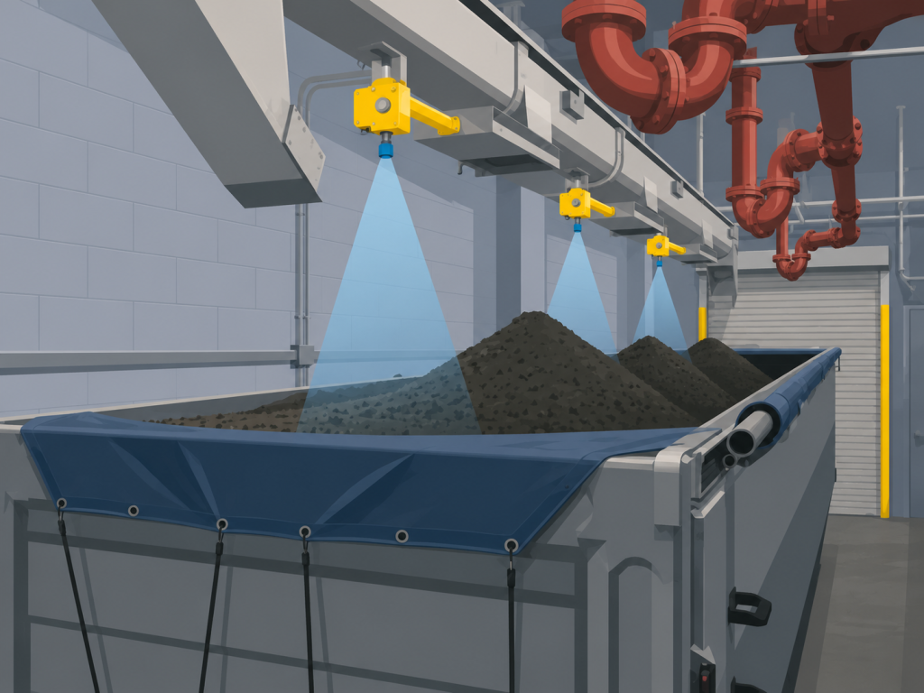
A municipal water treatment facility discharges dewatered sludge from a screw conveyor into a roll-off container. Operators currently inspect the container manually and stop the conveyor when the pile approaches the top edge.
The facility installs an RPS-409A-144 on a fixed steel gantry above the container. The sensor is positioned to the side of the discharge stream and aimed downward toward the expected high point of the sludge pile.
The 0–10 V output is connected to an analog input on the plant PLC. The PLC scales the signal into distance and uses two control thresholds:
- A high-level warning alerts the operator that the container is approaching capacity.
- A high-high threshold stops the sludge conveyor after the condition remains present for a defined time.
When a full container is removed, the sensor and cable remain attached to the gantry. The empty replacement container is positioned against fixed stops so the measurement point remains repeatable.
Because sludge consistency and pile shape vary, the facility tests the installation under normal loading conditions before relying on it for automatic shutdown.
Discuss Your Sludge Monitoring Application With Migatron
Contact Migatron to request an application review and determine whether the RPS-409A is appropriate for the installation.
Frequently Asked Questions
Can an ultrasonic sensor detect sludge without touching it?
Yes. The sensor measures the distance to the sludge surface using reflected sound. It does not require a probe, float, or mechanical component to contact the material.
Where should the sensor be mounted?
The sensor should be mounted on a fixed overhead bracket, gantry, or structural frame. A fixed mounting point allows the roll-off container to be removed and replaced without disconnecting or repositioning the sensor.
Should the sensor be mounted directly above the discharge point?
Generally, no. Falling sludge can interrupt the sound beam and may coat the sensing face. The sensor should be offset from the falling stream and aimed at a representative area of the pile.
Can the sensor estimate how full the container is?
The sensor directly measures distance rather than total container volume. A PLC can convert that distance into an estimated fill percentage, but accuracy depends on the container geometry and how evenly the sludge accumulates.
What happens if the sludge pile is uneven?
An uneven surface can produce changing measurements as the pile grows or shifts. Sensor location, beam alignment, signal averaging, and alarm delays should be evaluated during application testing.
Can multiple sludge containers be monitored?
Yes. A facility can connect sensors from multiple container stations to a PLC or SCADA system as part of a scalable sensor network. The control-system capacity, sensor spacing, cabling, and possible acoustic interaction should be reviewed before installation.