About Ultrasonics
Understanding Ultrasonics
Ultrasonic Sensing/Control Basics
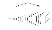
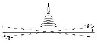
Ultrasonic signals are like audible sound waves, except the frequencies are much higher. Our ultrasonic transducers have piezoelectric crystals which resonate to a desired frequency and convert electric energy into acoustic energy and vice versa. The illustration shows how sound waves, transmitted in the shape of a cone, are reflected from a target back to the transducer. An output signal is produced to perform some kind of indicating or control function. A minimum distance from the sensor is required to provide a time delay so that the “echoes” can be interpreted. Variables which can affect the operation of ultrasonic sensing include: target surface angle, reflective surface roughness or changes in temperature or humidity. The targets can have any kind of reflective form – even round objects.
When used for sensing functions, the ultrasonic method has unique advantages over conventional sensors:
- Discrete distances to moving objects can be detected and measured.
- Less affected by target materials and surfaces, and not affected by color.
- Solid-state units have virtually unlimited, maintenance-free life.
- Can detect small objects over long operating distances.
- Resistance to external disturbances such as vibration, infrared radiation, ambient noise, and EMI radiation.
Two Ultrasonic Sensor Types
The following diagrams summarize the distinctions between proximity and ranging ultrasonic sensors:
Proximity Detection
An object passing anywhere within the preset range will be detected and generate an output signal. The detect point is independent of target size, material, or degree of reflectivity.
First Image-Object Detected
Second Image-Object Not Detected
Ranging Measurement
Precise distance(s) of an object moving to and from the sensor are measured via time intervals between transmitted and reflected bursts of ultrasonic sound. The example shows a target detected at six inches from the sensor and moving to 10 inches. The distance change is continuously calculated and outputted.
Target Angle
This term refers to the “tilt response” limitations of a given sensor. Since ultrasonic sound waves reflect off the target object, target angles indicate acceptable amounts of tilt for a given sensor. If an application requires a target angle beyond the capabilities of a single sensor, two sensors can be teamed up to provide an even broader angle of tilt.
Beam Spread
This term is defined as the area in which a round wand will be sensed if passed through the target area. This is the maximum spreading of the ultrasonic sound as it leaves the transducer.
Distance Hysteresis Option
Some standard proximity sensors can be furnished with a “hysteresis control” capability. Many hysteresis sensors have a fixed detect point equal to the sensor’s minimum range, and an adjustable turn off point up to the sensor’s maximum range. Consult factory for hysteresis option.
Thru-Beam Option
The TBT/TBR-600-40 is primarily a Thru-Beam sensor consisting of one transmit and one receive transducer, in separate and self-contained housings.
High Gain Option
The RPS-300 and 325 can be furnished with a high gain capability. This is denoted by the letter (G) in the part number. (Example: RPS-300G-14)
Analog Output Option
Analog outputs of 0-10 VDC and 4-20 mA are available in a variety of models. See the selection card and appropriate data sheet for details. Note: In some models, analog output is an option indicated by adding (-500) to the part number. (Example: RP S-100-14-500)
Analog Ranging Card
When connected to any RPS-100/300/325/326 proximity sensor, an RPS-500 ANALOG RANGING CARD converts proximity sensors into ranging sensors. It then measures discrete distances to a target within a selected range, then outputs one or more signals to a controller or computer.
DESCRIPTION RPS-500
OUTPUTS: Analog voltage (0-10 VDC) and current (4-20 mA), linearly proportional to target distance. It has adjustable zeroing and span control, plus inverting switch. Outputs are isolated up to 2500V. It is powered by 120VAC. ANALOG RANGING CARD RPS-500
Formulas
Effects of Temperature Change Formula
ADC = .0019 x D x F
ADC = Apparent Distance Change
D = Distance from transducer to target in inches
F = Change in temperature in Fahrenheit.
Temperature conversion Fahrenheit/Centigrade
Fº = 9/5Cº + 32Cº = 5/9(Fº – 32)
Sensor Selection
All units are furnished with mounting capabilities and an LED to indicate the output state. Also included is a 6-ft. cable. Optional cable lengths are available. All sensors can be easily interfaced with controllers or computers. Note that proximity sensors (RPS-100/300/325/326) can be quickly converted into ranging sensors via a simple connection to an RPS-500 Analog Ranging Card.